42 Results
View results:
Sort by:

The ASCE 7-22 Standard [1], Sect. 12.9.1.6 specifies when P-delta effects should be considered when running a modal response spectrum analysis for seismic design. In the NBC 2020 [2], Sent. 4.1.8.3.8.c gives only a short requirement that sway effects due to the interaction of gravity loads with the deformed structure should be considered. Therefore, there may be situations where second-order effects, also known as P-delta, must be considered when carrying out a seismic analysis.

This article will show you the Building Model add-on, which has been enhanced with one important advantage: calculating the center of mass and center of rigidity.
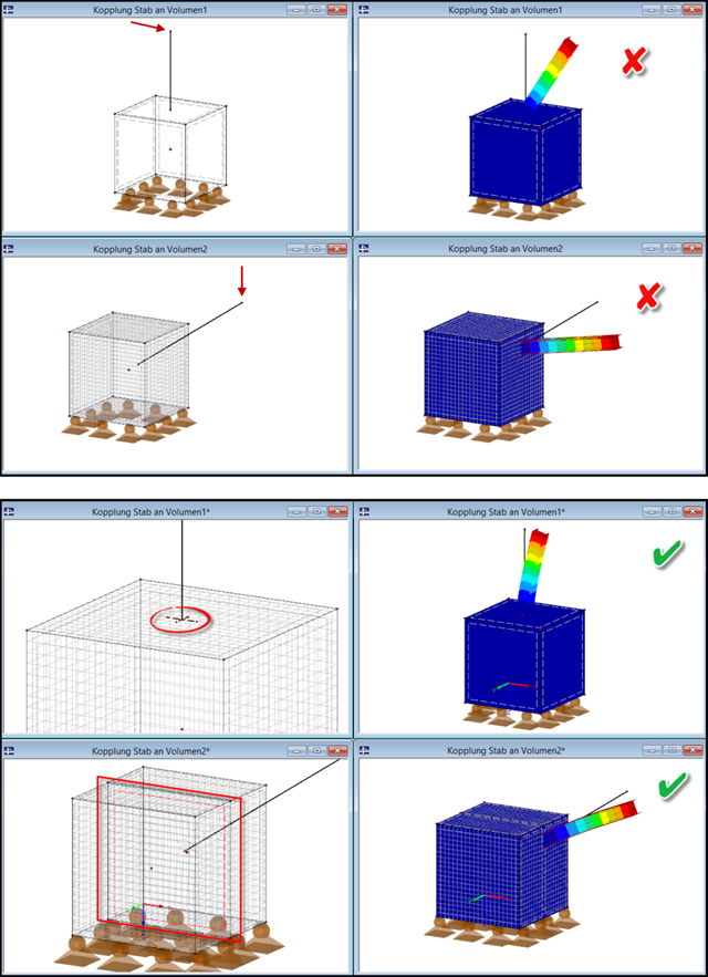
If a slender component (member) is to be connected to a massive component (solid), it is necessary to pay attention to the correct connection of both elements.

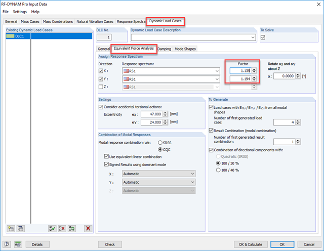
RF-/DYNAM Pro - Equivalent Loads allows you to determine the loads due to equivalent seismic loads according to the multi‑modal response spectrum method. In the example shown here, this was done for a multi‑mass oscillator.

The dialog box for editing load or result combinations is a non-modal dialog box. This means that after you open this dialog box, you can edit the combinations outside the dialog box as well. For manually defining or editing a combination, a separate dialog box can be opened parallel to the "Edit load cases and combinations" dialog box.
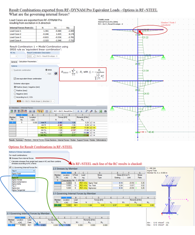
Result combinations exported from RF‑/DYNAM Pro – Equivalent Loads are generated by superimposing the results from the individual modal responses. For this, the SRSS rule can be used as "equivalent linear combination". When result combinations are used in RF‑/STEEL, two options are available for calculating stresses. In the first option, the results from the result combinations are used directly. This is done line by line, for each maximum and minimum controlling internal force. In the second option, stresses are determined from the individual load cases. The quadratic superposition rule is then performed again in RF-/STEEL.

The dynamic analysis in RFEM 6 and RSTAB 9 is divided into several add-ons. The Modal Analysis add-on is a prerequisite for all other dynamic add-ons, since it performs the natural vibration analysis for member, surface, and solid models.

Given that realistic determination of the soil conditions significantly influences the quality of the structural analysis of buildings, the Geotechnical Analysis add-on is offered in RFEM 6 to determine the soil body to be analyzed.
The way to provide data obtained from field tests in the add-on and use the properties from soil samples to determine the soil massifs of interest was discussed in Knowledge Base article “Creation of the Soil Body from Soil Samples in RFEM 6”. This article, on the other hand, will discuss the procedure to calculate settlements and soil pressures for a reinforced concrete building.

RSECTION 1 is a stand-alone program for determining section properties for both thin-walled and massive cross-sections, as well as for performing a stress analysis. In addition, the program can be connected to both RFEM and RSTAB: sections from RSECTION are available in the RFEM/RSTAB libraries, and internal forces from RFEM/RSTAB can be imported into RSECTION.
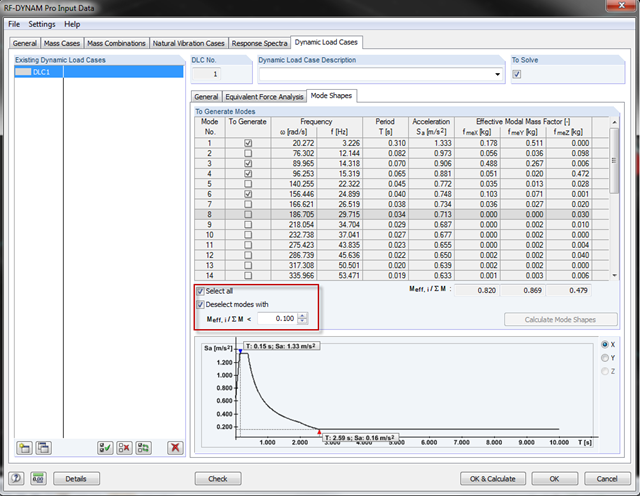
With the latest version of RF‑/DYNAM Pro, you can exclude the mode shapes from the seismic design. In most standards, there are provisions to exclude the effective modal mass factors that are too small. The "Mode Shapes" tab offers the option to specify the factor and to disregard the mode shapes automatically.
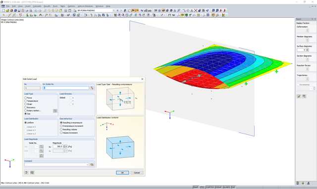
In theory, an ideal gas consists of freely moving mass particles without extension in a volume space. In this space, each particle moves at a speed in one direction. The collision of one particle with another particle or the volume limitations leads to a deflection and a change in the speed of the particles.

The new RF‑/DYNAM Pro - Natural Vibrations module has been available since RFEM version 5.04.xx and RSTAB version 8.04.xx were released. Masses can now be imported directly from load cases and load combinations.
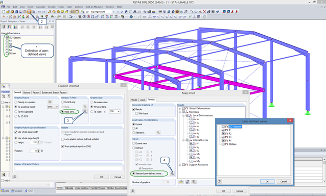
User-defined views are a very useful tool for effective modeling, as the previously selected and adapted objects appear directly with a click of the mouse. These objects can also be used easily to create informative and clearly arranged result graphics. With just a few clicks, you can create all result graphics at once using the mass print function.

This article presents the basic concepts in structural dynamics and their role in the seismic design of structures. Great emphasis is given to explaining the technical aspects in an understandable way, so that readers without deep technical knowledge can gain an insight into the subject.

The add-on modules for designing structural member components according to national, European, and international standards also show design results in addition to numerical output in tables graphically, as diagrams displayed on the framework.

Modal analysis is the starting point for the dynamic analysis of structural systems. You can use it to determine natural vibration values such as natural frequencies, mode shapes, modal masses, and effective modal mass factors. This outcome can be used for vibration design, and it can be used for further dynamic analyses (for example, loading by a response spectrum).

The modal relevance factor is a result of the linear stability analysis and qualitatively describes the degree of participation of individual members in a specific mode shape.

The number of National Annexes for Eurocode 2 with regard to the design of reinforced concrete cross-sections has been extended since SHAPE-MASSIVE 6.54. Therefore, the following NAs of EN 1992-1-1:2004 + AC:2010 are available:
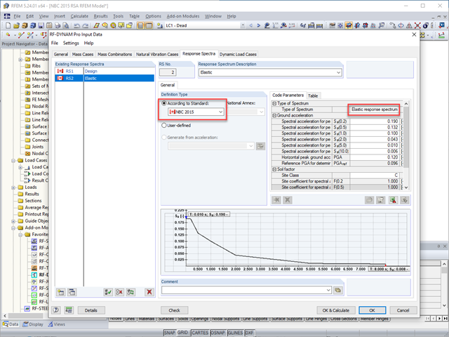
The National Building Code of Canada (NBC) 2015 Article 4.1.8.7 provides a clear procedure for earthquake methods of analysis. The more advanced method, the Dynamic Analysis Procedure in Article 4.1.8.12, should be used for all structure types except those that meet the criteria set forth in 4.1.8.7. The more simplistic method, the Equivalent Static Force Procedure (ESFP) in Article 4.1.8.11, can be used for all other structures.

The National Building Code of Canada (NBC) 2020 Article 4.1.8.7 provides a clear procedure for earthquake methods of analysis. The more advanced method, the Dynamic Analysis Procedure in Article 4.1.8.12, should be used for all structure types except those that meet the criteria set forth in 4.1.8.7. The more simplistic method, the Equivalent Static Force Procedure (ESFP) in Article 4.1.8.11, can be used for all other structures.
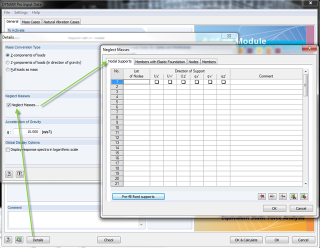
In the DYNAM Pro add‑on module for RSTAB, you can now neglect masses that may have a negative effect on the equivalent mass factor when calculating eigenvalues. To do this, you can disable the masses under [Details]. These include primarily mass points located in the support of the structures.
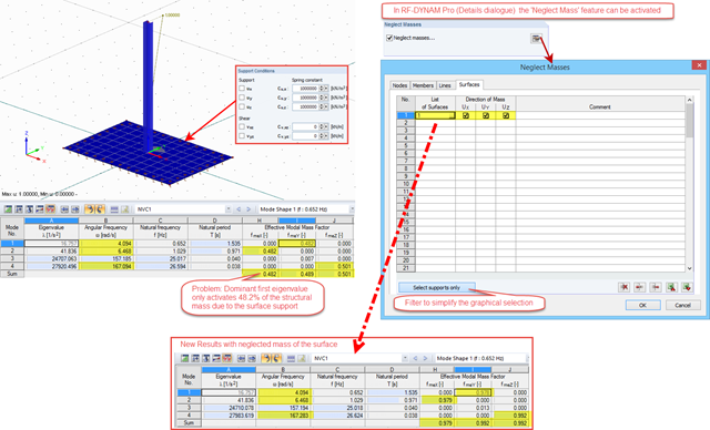
As of the version 5.06.1103, masses of nodes, lines, members, and surfaces can be neglected in RF‑DYNAM Pro. The setting to activate this feature can be found in the Details dialog box; the neglected masses are valid for all defined mass cases.

The “Modal Analysis” add-on in RFEM 6 allows you to perform modal analysis of structural systems, thus determining natural vibration values such as natural frequencies, mode shapes, modal masses, and effective modal mass factors. These results can be used for vibration design, as well as for further dynamic analyses (for example, loading by a response spectrum).

In order to consider inaccuracies regarding the position of masses in a response spectrum analysis, standards for seismic design specify rules that have to be applied in both the simplified and multi-modal response spectrum analyses. These rules describe the following general procedure: The story mass must be shifted by a certain eccentricity, which results in a torsional moment.
As gravity loads act on a structure, lateral displacement occurs. In turn, a secondary overturning moment is generated as the gravity load continues to act on the elements in the laterally displaced position. This effect is also known as "P-Delta (Δ)". Sec. 12.9.1.6 of the ASCE 7-16 Standard and the NBC 2015 Commentary specify when P-Delta effects should be considered during a modal response spectrum analysis.
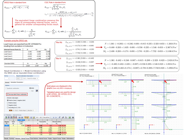
The modal results of a response spectrum analysis are combined with quadratic combination rules, and in RF‑/DYNAM Pro, the SRSS and the CQC rules are available. The default setting modifies the quadratic expressions into equivalent linear combinations. The advantage of this option is that the corresponding internal forces keep their signs and are often much smaller, compared to the standard SRSS or CQC rules. The standard SRSS and CQC rules are on the conservative side and the "equivalent linear combinations" are recommended.

You can use the stand-alone program RSECTION to determine the section properties for any thin-walled and massive cross-sections, as well as to perform a stress analysis. The previous Knowledge Base article titled "Graphical/Tabular Creation of User-defined Cross-sections in RSECTION 1" discussed the basis of defining cross-sections in the program. This article, on the other hand, is a summary of how to determine the section properties and perform a stress analysis.

Seismic Analysis in RFEM 6 is possible using the modal analysis and the response spectrum analysis add-ons. As a matter of fact, the general concept of the earthquake analysis in RFEM 6 is based on the creation of a load case for the modal analysis and the response spectrum analysis, respectively. The standard groups for these analyses are set in the Standards II tab of the model’s Base Data.
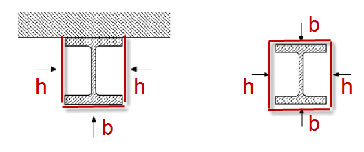
For unprotected I‑sections, the standard provides the correction factor ksh according to Equation 4.26a in Section 4.2.5.1 (2) to consider the shadowing effect. The term [Am/V]b is used there. This section factor includes Am, which represents the box enclosing the cross‑section (Index b = boxed). In the case of a three-sided fire exposure (a girder with a massive ceiling), the flange surface not exposed to fire is not taken into account when determining [Am/V]b.

The SHAPE‑THIN and SHAPE‑MASSIVE cross-section programs are suitable for determining the cross-section properties of common thin-walled or thick-walled sections. These cross-section properties are also available for further analyses in RSTAB and RFEM.